SLA-17K Spec Sheet / Product Catalog
Linear Actuator
SLA-17K Linear Actuator
IP67 industrial DC linear actuator with up to 17,000 N dynamic force, 12V/24V/36V/48V DC, ball-screw or ACME-screw codes A–J, stroke 50–1,000 mm, standard…
Key specifications
- Maximum load
- 17000 N
- Stroke
- 50 – 1000 mm (customizable)
- Speed
- 6.5 mm/s – 35 mm/s (no load, by code)
- Voltage
- DC 12 V, 24 V, 36 V or 48 V
- IP rating
- IP67
- Duty cycle
- 20–35% (by transmission code)
Product overview
IP67 industrial DC linear actuator with up to 17,000 N dynamic force, 12V/24V/36V/48V DC, ball-screw or ACME-screw codes A–J, stroke 50–1,000 mm, standard manual override and optional Hall or analog feedback.
- Maximum load
- 17000 N
- Stroke
- 50 – 1000 mm (customizable)
- Speed
- 6.5 mm/s – 35 mm/s (no load, by code)
- Voltage
- DC 12 V, 24 V, 36 V or 48 V
- IP rating
- IP67
- Feedback
- Optional Hall, analog, end-stop or magnetic switches
Applications
- Construction vehicles and machinery
- Agricultural machinery
- Industrial automation
- Outdoor power equipment
Benefits
- Industrial electric linear actuator, max dynamic force 17,000 N (Code A ball screw)
- Working voltage: 12V / 24V / 36V / 48V DC
- IP67 weather protection
- Ball-screw codes A–E and ACME-screw codes F–J
- Stroke 50–1,000 mm; retracted length from stroke + 200 mm plus catalog additions
- Standard manual override for motion without power
- Optional Hall, analog, end-stop signal or magnetic switches (potentiometer is not offered)
- Electronic overload protection and replaceable weatherproof cable module
Technical specifications
| Maximum load | 17000 N |
|---|---|
| Stroke | 50 – 1000 mm (customizable) |
| Stroke options | 50–1,000 mm (customizable) |
| Speed | 6.5 mm/s – 35 mm/s (no load, by code) |
| Voltage | DC 12 V, 24 V, 36 V or 48 V |
| IP rating | IP67 |
| Duty cycle | 20–35% (by transmission code) |
| Feedback | Optional Hall, analog, end-stop or magnetic switches |
| Mounting type | F01–F14 / R01–R07; sample outline Ø20 |
| Noise level | ≤65 dB |
| Motor type | Brushed DC |
| Manual override | Yes (standard) |
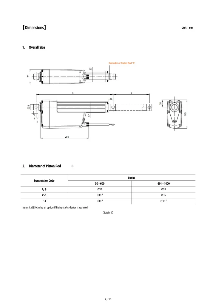
Dimensions & installation drawing
Performance matrix
| No-load speed | Full-load speed | Thrust | Self-locking force |
|---|---|---|---|
| 6.5 mm/s | 5 mm/s | 17000 N | 20000 N |
| 7 mm/s | 5 mm/s | 12000 N | 15000 N |
| 9 mm/s | 6.5 mm/s | 13500 N | 15000 N |
| 10 mm/s | 7 mm/s | 10000 N | 12000 N |
| 14 mm/s | 9 mm/s | 10000 N | 12000 N |
| 14 mm/s | 8 mm/s | 7500 N | 10000 N |
| 18 mm/s | 13 mm/s | 7500 N | 10000 N |
| 23 mm/s | 13 mm/s | 5000 N | 8000 N |
| 28 mm/s | 20 mm/s | 5000 N | 8000 N |
| 35 mm/s | 23 mm/s | 3500 N | 5000 N |
Configuration options
| Parameter | Condition | Add (mm) |
|---|---|---|
| a. Basic | all | ≥ stroke + 200 |
| b. Transmission | A, B | + 30 |
| b. Transmission | C–J | + 0 |
| c. Stroke band | 30–300 mm | + 0 |
| c. Stroke band | 301–600 mm | + 50 |
| c. Stroke band | 601–1,000 mm | + 100 |
| d. Mounting ends | F01–F12 | + 0 |
| d. Mounting ends | F13, F14 | + 40 |
| d. Mounting ends | R01–R07 | + 0 |
Installation, electrical and use information
External Dimensions · Installation Size · Mounting Connectors · Manual Override and Cable
External Dimensions
The spec-sheet overall-size drawing shows a motor/gear housing about 250 mm long × 76 mm wide × 149 mm high, a 57 mm piston-rod housing, a 25 mm front-hole offset from the tube end, and a spherical rear end with a Ø20 hole on that sample outline. Front and rear hole orientation is 0° or 90°.
Installation Size
Retracted installation length L ≥ a + b + c + d. Basic length is stroke + 200 mm. Extra length depends on gearset, stroke band and the chosen front/rear ends.
| Term | Condition | Add (mm) |
|---|---|---|
| a. Basic | all | ≥ stroke + 200 |
| b. Transmission | A, B | + 30 |
| b. Transmission | C–J | + 0 |
| c. Stroke band | 30–300 mm | + 0 |
| c. Stroke band | 301–600 mm | + 50 |
| c. Stroke band | 601–1,000 mm | + 100 |
| d. Mounting ends | F01–F12 | + 0 |
| d. Mounting ends | F13, F14 | + 40 |
| d. Mounting ends | R01–R07 | + 0 |
- F01–F12 with stroke ≤100 mm: minimum L is 300 mm.
- F13/F14 with stroke ≤100 mm: minimum L is 340 mm.
- Example: 400 mm stroke, Code A, F13 + R01 → L ≥ 400 + 200 + 30 + 50 + 40 = 720 mm.
- Example: 50 mm stroke, Code C, F01 + R01 → L ≥ 300 mm (short-stroke minimum).
If you need stroke and installation length to be adjustable after delivery, the spec sheet allows magnetic switches; then both end limits must be handled by your controller.
Mounting Connectors
Front rod ends F01–F14 and rear motor ends R01–R07 are catalogued. Cross-hole codes use Ø12.2 / Ø13.2 / Ø14.2 mm; F11/R06 are male M16×2; F12/R07 are female M16×2; F13/F14 are joint bearings (Ø12-H7 / Ø16-H7). Confirm the end codes on the quote — do not assume the Ø20 sample outline is the only hole.
Manual Override and Cable
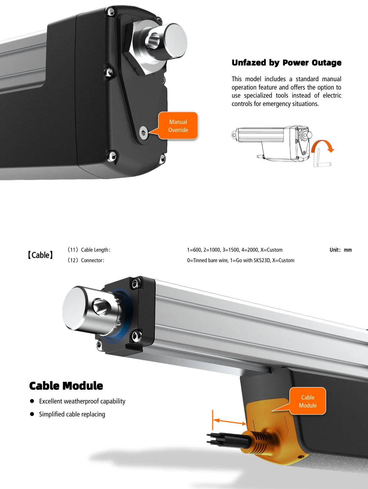
SLA-17K includes a standard manual-operation feature so the actuator can still extend or retract during a power outage. Use the dedicated override port with the specified tool. The cable module is weatherproof and replaceable.
Download center
FAQ
What is the SLA-17K?
The SLA-17K is an Elerover linear actuator rated IP67.
Does Elerover manufacture the SLA-17K?
Yes. Elerover is a linear actuator manufacturer and supplier. This model supports OEM configuration options listed in the product data—share your duty cycle and quantity for a factory quote.
What are the key specifications of the SLA-17K?
Key ratings from the product specifications include voltage 12V / 24V / 36V / 48V DC, load 17000 N, stroke 50–1,000 mm (customizable), protection IP67. See the Technical Specifications section on this page for the full table.
How do I request a quote for the SLA-17K?
Send load, stroke, voltage, IP rating, duty cycle, quantity and any OEM options you need via the contact form or WhatsApp.
Request a quote
Quote context
Related products
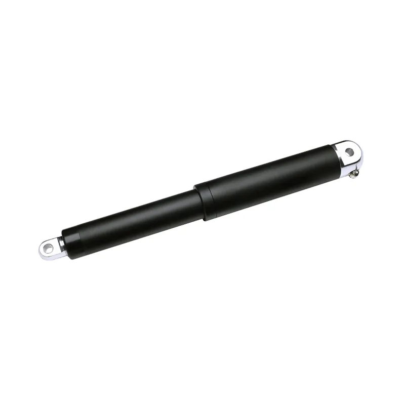
12 V DC 24 V DC SLA52M 6,000 N IP66/IP67M/IP69K waterproof tubular linear actuator
- Force
- 6,000 N
- Stroke
- Up to 500 mm
- Voltage
- 12 V / 24 V DC
- IP
- IP66 / IP67M / IP69K
SLA52M Ø52 mm waterproof tubular / in-line linear actuator (datasheet model SLA-T52) — up to 6000 N / 600 kg / 1349 lbs, 12V / 24V DC, stroke up to 500 mm, max 88 mm/s, IP66 / IP67M / IP69K. Ideal for skylights, smoke vents and yacht automation.
View Details →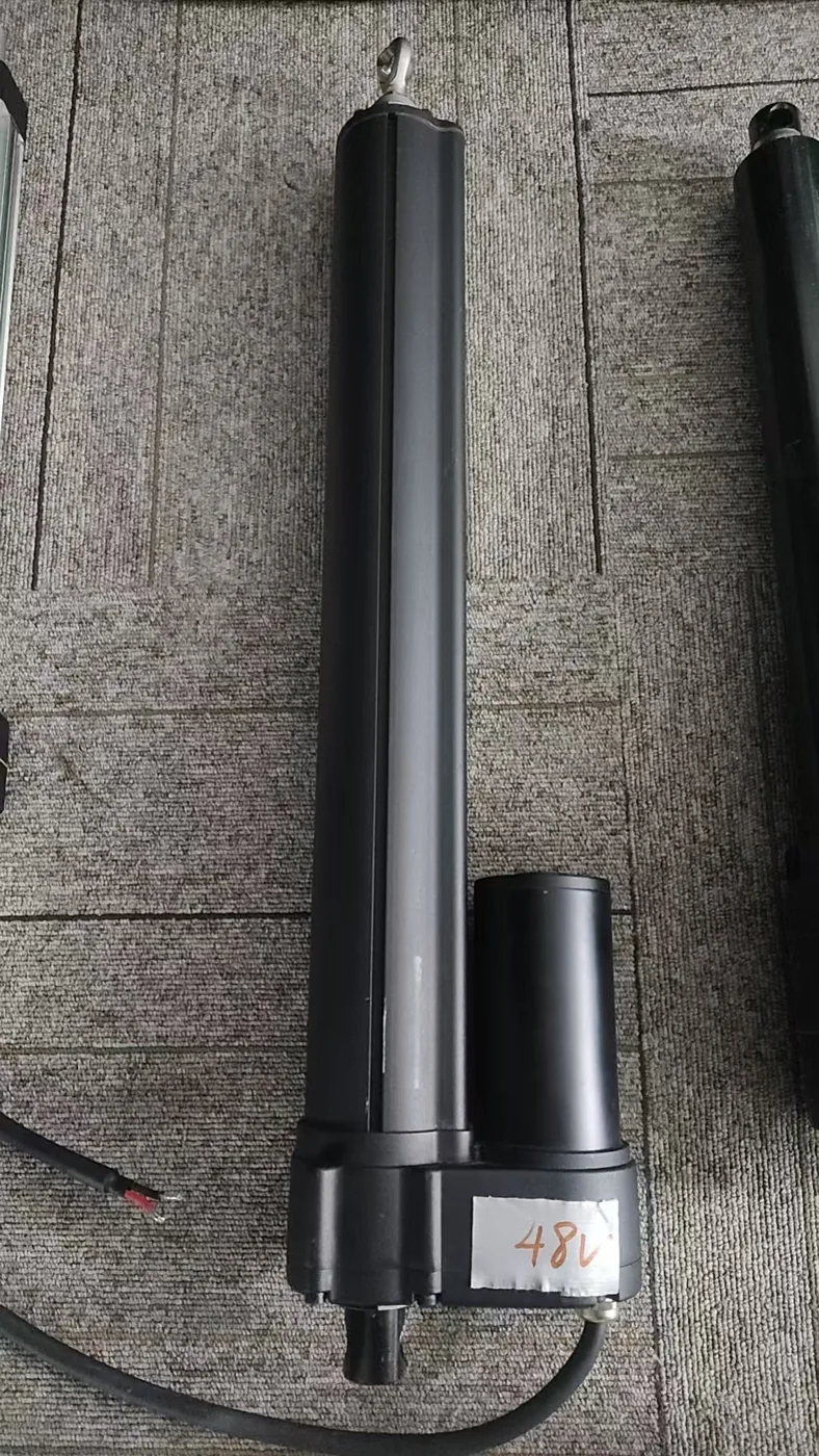
SLA08G Linear Actuator
- Force
- 12,000 N
- Stroke
- 50 – 1000 mm (customizable)
- Voltage
- DC 12 V, 24 V, 36 V or 48 V
- IP
- IP67
IP67 industrial DC linear actuator with up to 12,000 N dynamic force, 12V/24V/36V/48V DC, ball-screw or ACME-screw codes A–K, stroke 50–1,000 mm, standard manual override and optional Hall or potentiometer feedback.
View Details →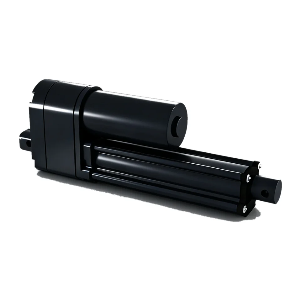
SLA06S-WP IP67 waterproof linear actuator
- Force
- 3,500 N
- Stroke
- Custom; retracted length S…
- Voltage
- DC 12 V or DC 24 V
- IP
- IP67
IP67 waterproof industrial linear actuator with up to 3500N push/pull, powder-metallurgy gears and built-in potentiometer feedback. 12V/24V DC, 60W motor, 3–170 mm/s, limit switches.
View Details →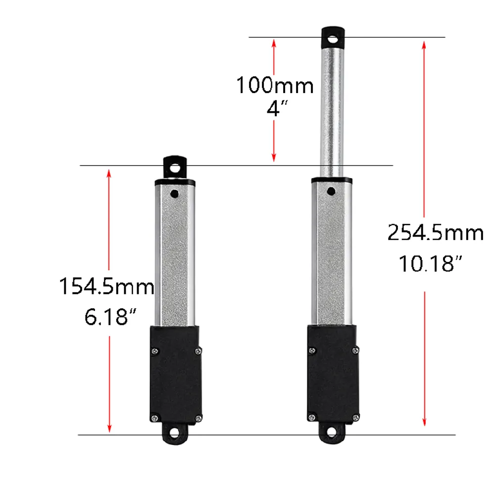
SLA-T01 100mm stroke linear actuator
- Force
- 188 N
- Stroke
- 100 mm
- Voltage
- 6 V / 12 V / 24 V DC
- IP
- IP54
DC 6V/12V/24V household miniature linear actuator with 100mm stroke, max thrust 188N / 42 lbs. Compact, quiet and suitable for furniture, medical and OEM applications.
View Details →Compatible controllers
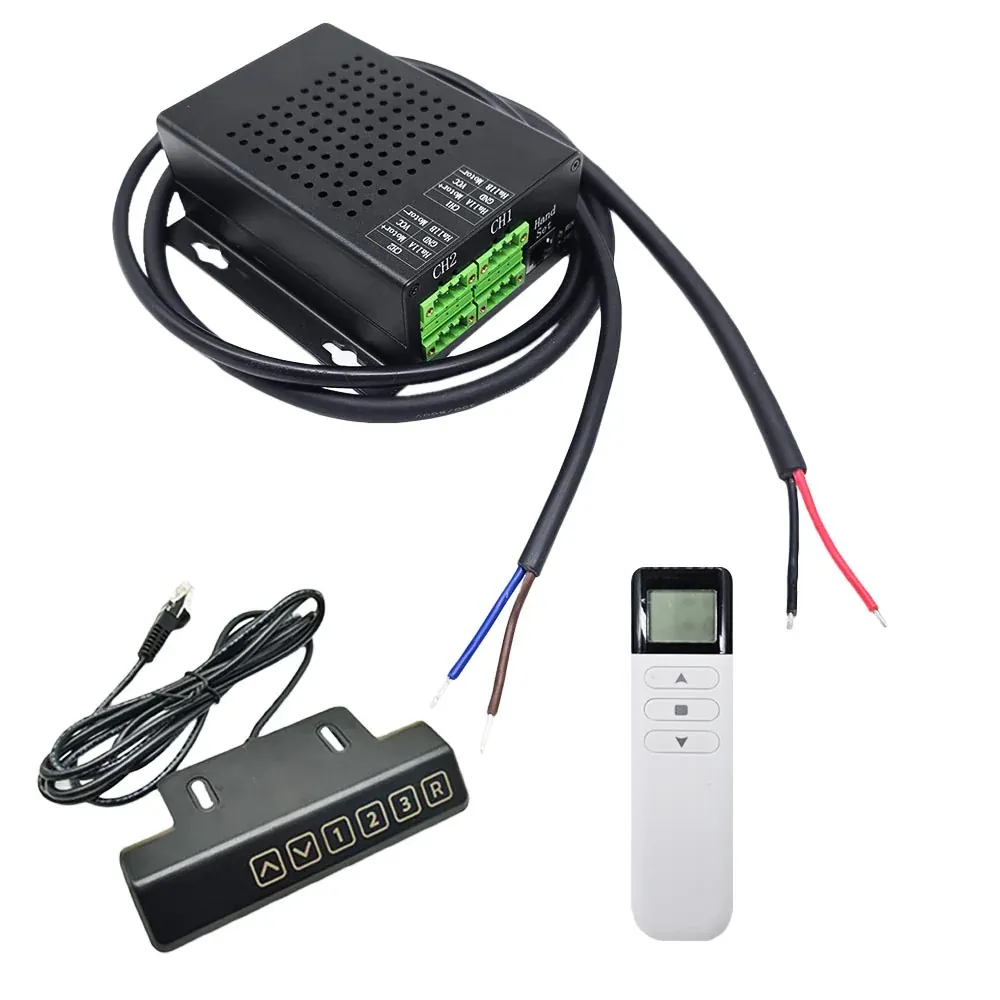
SLA-SCN2-HC One-Control-Two Synchronous Controller
SLA-SCN2-HC synchronous controller for two Hall-sensor linear actuators: 12–48 VDC, 25 A, touch handle and 2.4 GHz remote, 3 memory positions, LED stroke display.
View Details →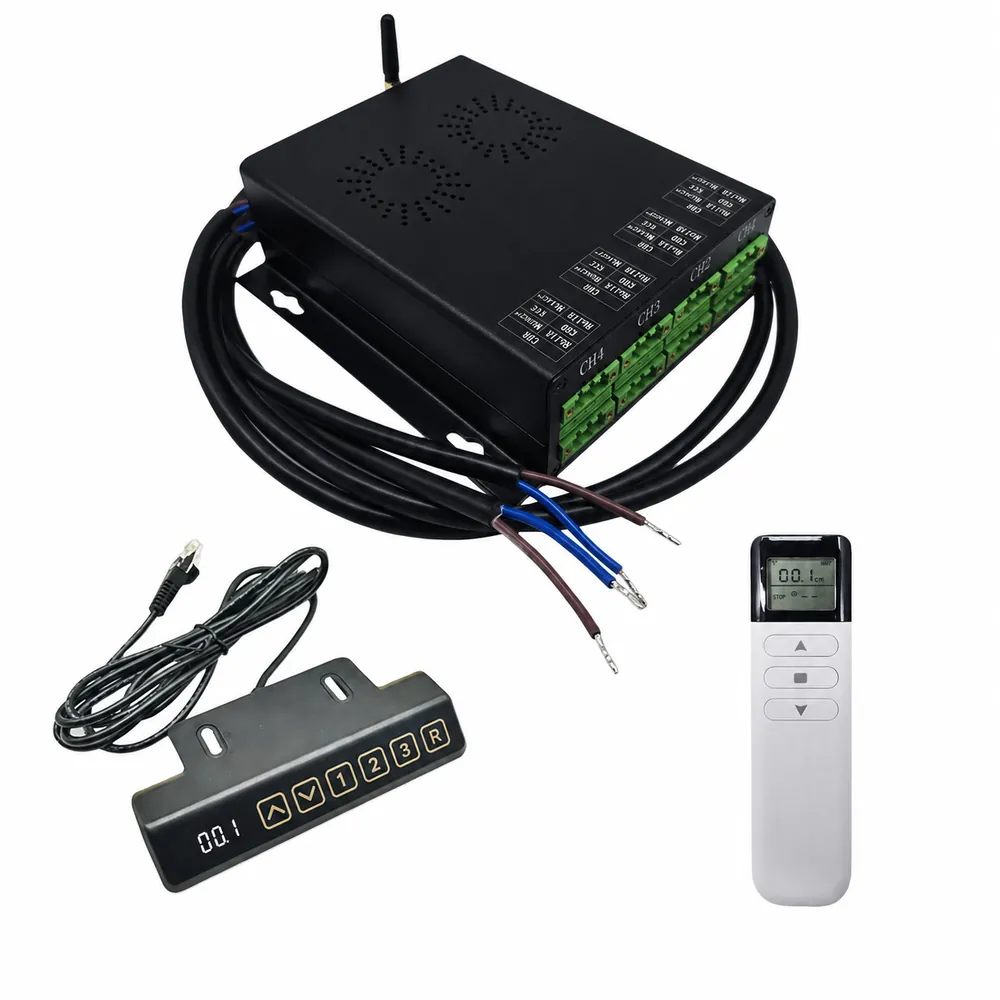
SLA-SCN4-HC One-Control-Four Synchronous Controller
SLA-SCN4-HC synchronous controller for four Hall-sensor linear actuators: 12–48 VDC, 25 A, touch handle and 2.4 GHz remote, 3 memory positions, LED stroke display.
View Details →