SCN4-R Four Linear Actuator Synchronous Controller Guide
How the SCN4-R synchronizes up to four feedback linear actuators on 12–48V DC—features, specs, control options, wiring notes, and OEM selection tips.
Introduction
When four linear actuators share one platform, simply paralleling the motors is not enough. Load differences change motor speed, the frame starts to tilt, and mechanical stress builds up. A four linear actuator synchronous controller closes that gap by reading position feedback and correcting each channel while the system moves.
This article introduces Elerover’s SCN4-R controller: what it does, the published electrical envelope, how you can command it (wireless remote, wired buttons, toggle switch, or PLC relays), and what to prepare for an OEM quotation.
What the SCN4-R Does
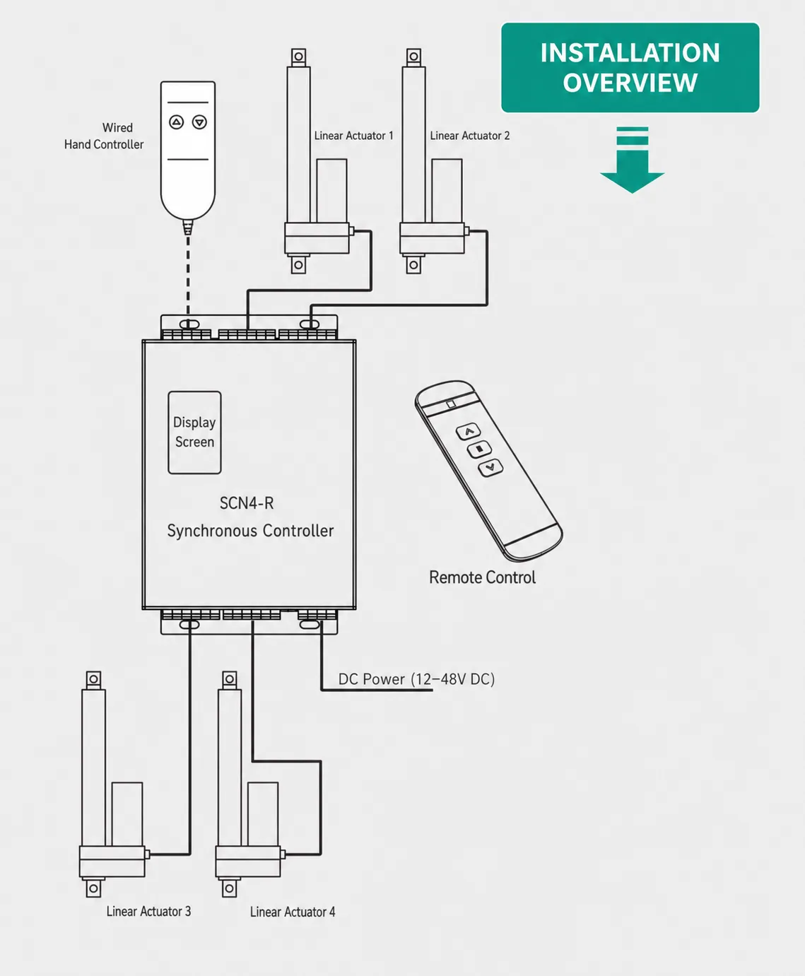
The SCN4-R is built to operate one to four compatible DC feedback linear actuators as a coordinated extend/retract group. It compares feedback from each connected actuator and adjusts individual motor outputs so the structure travels together.
According to the product specification, synchronization error can be held within three feedback pulses—typically less than 1 mm—when the controller is correctly matched, wired, and calibrated with compatible actuators.
That closed-loop approach suits lifting tables, adjustable fixtures, multi-point frames, and other machines where independent motor drive would create skew.
Key Features at a Glance
- Four-channel synchronized motion for compatible feedback actuators
- 12–48V DC input; output voltage follows the supply
- Up to 10A per motor channel (published maximum)
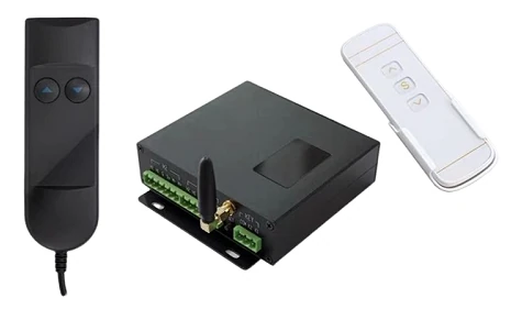
- Command options: 2.4G wireless remote, wired hand controller / push buttons, toggle switches, PLC relay contacts
- Position-feedback inputs on each actuator port
- Adjustable overcurrent protection (8A default) plus short-circuit, motor-stall, and feedback-fault protection
- Power-loss data retention (specification lists up to 40 million storage cycles)
- Digital display for commissioning and status
- Aluminum-alloy enclosure with plug-in terminals
- Jog / self-locking modes, selectable for the machine interface
Technical Specifications
| Parameter | SCN4-R specification |
|---|---|
| Product type | Four-channel linear actuator synchronous controller |
| Controlled actuators | 1–4 |
| Input voltage | 12–48V DC |
| Output voltage | Same as input |
| Max output current | 10A per motor channel |
| Synchronization accuracy | Within 3 feedback pulses; specified as less than 1 mm |
| Feedback input | Yes |
| Wireless control | 2.4G remote |
| External command | Wired buttons, toggle switches, or PLC relay contacts |
| Default overcurrent | 8A, adjustable |
| Protections | Short-circuit, motor-stall, encoder/feedback fault |
| Enclosure | Aluminum alloy, black |
| Operating temperature | -20°C to +65°C |
| Operating modes | Jog / self-locking, selectable |
| Controller body size | Approx. 114.5 × 159 × 33 mm |
| Overall mounting length | Approx. 169 mm |
Selection note: Confirm actuator load, speed, stroke, duty cycle, feedback type, and working voltage before ordering. System performance depends on matched actuators, power supply, wiring, and mechanical structure.
Interfaces and Connections
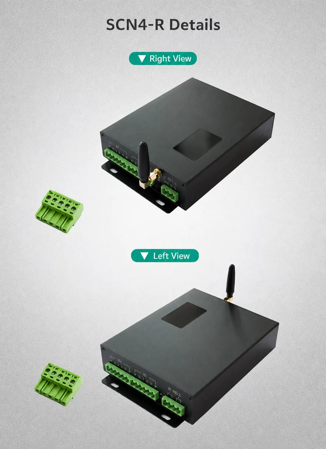
Ports M1–M4 each provide motor power and feedback wiring. Side panels carry DC power, status LEDs, antenna, SET, and the external command terminal.
| Interface | Function |
|---|---|
| M1–M4 | Motor power and position feedback for actuators 1–4 |
| DC POWER | 12–48V DC input |
| KEY: COM / K1 / K2 | External extend/retract from switches or relay contacts |
| SET | Setup, pairing, or calibration |
| Antenna | 2.4G wireless remote |
| Red LED | Power |
| Green LED | Controller status |
Important: Observe DC polarity marked on the housing. Reverse connection is not allowed. Disconnect power before wiring or changing terminals.
Control Methods
2.4G wireless remote
Raise, lower, or stop synchronized actuators without a fixed station—useful for mobile equipment, demos, and local commissioning.
Wired buttons or hand controller
Momentary push buttons on COM / K1 / K2 give a simple industrial panel interface.
PLC relay control
Potential-free PLC contacts can drive the same command inputs so the four-actuator group sits inside a larger automated sequence—without the PLC driving the motors directly.
Toggle-switch control
Suitable toggle switches can use jog or self-locking behavior based on machine logic and safety design.
Typical Applications
- Industrial lifting tables and work platforms
- Height-adjustable machinery and production fixtures
- Multi-point lifting frames
- Solar or equipment positioning systems
- Large ventilation hatches and access panels
- Agricultural and material-handling equipment
- Medical / care equipment (application-specific validation required)
- Custom OEM machines that need synchronized DC actuator motion
The controller does not set lifting capacity by itself. Capacity depends on the actuators, mounting geometry, load distribution, structural stiffness, and safety factor.
How to Select a Compatible System
Use actuators with the same voltage, motor type, stroke, speed, gear ratio, and feedback format. Mechanics should start from equivalent reference positions and carry a reasonably balanced load.
Before requesting a quote, prepare:
- Input voltage (12V / 24V / 36V / 48V DC)
- Actuator count (1–4)
- Load per actuator and total system load
- Stroke and required speed under load
- Feedback type and pulse information
- Duty cycle and operating frequency
- Preferred control method (remote, buttons, switch, or PLC)
- Cable lengths and environment
Basic Installation Workflow
- Mount the controller in a dry, ventilated location using the flanges.
- Install matched actuators and confirm free mechanical travel.
- With power off, wire actuators to M1–M4.
- Connect wired control, switch, or PLC relays if used.
- Connect a correctly sized 12–48V DC supply with correct polarity.
- Pair the wireless remote and complete setup / synchronization.
- Test unloaded or at low load first; confirm direction, current, and sync before full duty.
Closing
If your machine needs two, three, or four linear actuators to lift or position one structure together, the SCN4-R is a practical starting point for a synchronized DC motion system—especially when you need wireless, panel, or PLC command options on a 12–48V supply.
Send actuator voltage, load, stroke, speed, feedback signal, quantity, and control method. We can check compatibility and recommend a controller, actuator, and wiring package for your OEM project.
Browse related motion controllers or request a quote for datasheet, wiring confirmation, sample evaluation, or volume pricing.
FAQ
Can one SCN4-R controller synchronize four linear actuators?
Yes. The SCN4-R can control one to four compatible feedback linear actuators and continuously correct position differences during travel.
Does the SCN4-R work with 12V and 24V linear actuators?
Yes. The specified input range is 12–48V DC, and motor output voltage follows the input. The supply must match the actuators’ rated voltage.
What is the maximum current per actuator channel?
The published maximum is 10A per motor channel. The default overcurrent setting is 8A and can be adjusted to suit the selected actuators.
Can ordinary two-wire actuators without feedback be synchronized?
True closed-loop synchronization needs compatible position feedback from each actuator. Basic two-wire motors without feedback cannot provide that data.
Can a PLC control the SCN4-R?
Yes. Potential-free PLC relay contacts can command extend and retract through the COM, K1, and K2 inputs.
What synchronization accuracy is specified?
The specification lists an error within three feedback pulses—typically less than 1 mm in the published configuration. Actual accuracy depends on matching, load balance, wiring, and calibration.
More Articles
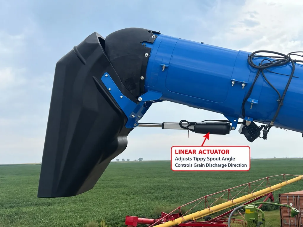
How an Electric Linear Actuator Adjusts an Unloading Auger Tippy Spout
Learn how an electric linear actuator can adjust an unloading auger tippy spout to improve grain discharge direction and trailer loading control.
Read Article →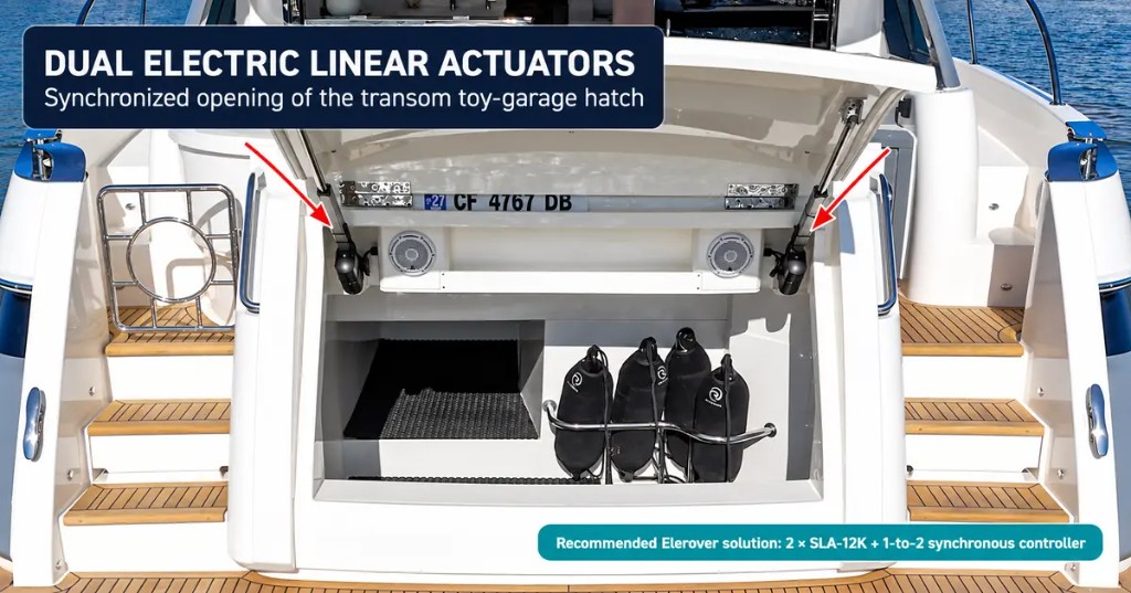
Dual Linear Actuators for Yacht Toy-Garage Hatches | SLA-12K
See how two synchronized electric linear actuators can open a yacht transom toy-garage hatch and how Elerover configures the SLA-12K system.
Read Article →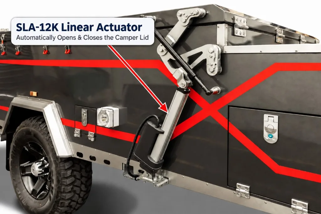
SLA-12K Linear Actuator for Automatic Camper Trailer Lids
See how a 12V or 24V SLA-12K heavy-duty linear actuator can automate the opening and closing of camper trailer lids and folding roof systems.
Read Article →