SLA-12K Heavy-Duty Linear Actuator Selection Guide
Learn how to select the SLA-12K 12,000 N heavy-duty linear actuator by load, speed, stroke, voltage, duty cycle, feedback and installation geometry.
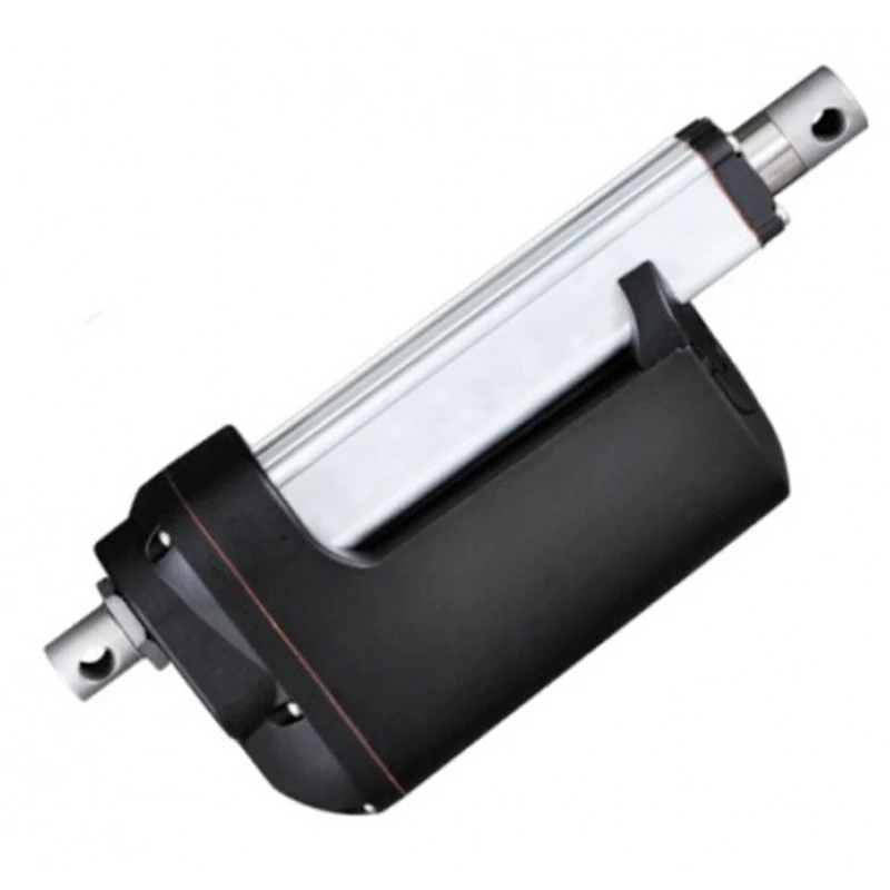
The SLA-12K converts DC motor rotation into controlled linear movement and can replace hydraulic or pneumatic cylinders in suitable applications. The correct version is determined by the complete mechanism—not by maximum thrust alone.
At a glance: 12,000 N maximum push force (low speed) · 12 V / 24 V DC · 50–700 mm standard strokes (custom on request) · IP66 reference enclosure rating.
What is the SLA-12K?
The SLA-12K is designed to lift, push, pull or position heavy loads. Key capabilities include:
- Industrial motion — suitable for lifting, tilting, opening, closing and positioning mechanisms
- Configurable travel — multiple stroke and installation-length options can match different machines
- Position feedback — optional potentiometer or Hall feedback supports positioning and synchronization
- Manual operation — an optional manual override can support emergency movement during power loss
Typical application areas include industrial hatches, lifting platforms, agricultural equipment, solar-tracking structures, mobile machinery, material handling and automated positioning systems.
12,000 N depends on speed
A lower-speed gearbox provides more force. A higher-speed configuration moves faster but carries less load. Therefore, “12,000 N maximum thrust” does not apply to every available speed.
Simple conclusion: You cannot choose 60 mm/s and still expect 12,000 N. Select the required force first, then choose the fastest compatible configuration.
| No-load speed | Full-load speed | Maximum push force | Self-locking force |
|---|---|---|---|
| 6 mm/s | 5 mm/s | 12,000 N | 15,000 N |
| 8 mm/s | 6 mm/s | 11,000 N | 12,000 N |
| 12 mm/s | 9 mm/s | 10,000 N | 12,000 N |
| 16 mm/s | 10 mm/s | 7,000 N | 8,000 N |
| 20 mm/s | 11 mm/s | 6,500 N | 8,000 N |
| 25 mm/s | 14 mm/s | 5,000 N | 6,000 N |
| 38 mm/s | 24 mm/s | 3,200 N | 4,000 N |
| 60 mm/s | 30 mm/s | 2,000 N | 3,000 N |
Reference values—confirm the final production configuration before ordering.
12,000 N is not automatically “lifting 1,200 kg”
Twelve thousand newtons is approximately the gravitational force of 1,200 kg under ideal conditions. A real hinged, tilted or lever-operated mechanism may require much more actuator force.
The actual requirement depends on:
- The distance between the load’s centre of gravity and the pivot
- The actuator mounting distance from the pivot
- The pushing angle at the most difficult point of travel
- Friction, wind, snow, impact and acceleration
- Whether the actuator is pushing or pulling
What to send us: Provide a dimensioned side-view drawing showing the pivot, load centre, actuator mounting points and fully open/closed positions.
How to choose the correct stroke
- Measure the closed position — record the pin-to-pin distance between both mounting points.
- Measure the open position — record the same distance after the mechanism reaches its target position.
- Calculate minimum travel — the difference between the two measurements is the minimum required stroke.
- Check installation length — confirm the retracted actuator body fits into the available space.
- Check alignment — long strokes need careful guidance to prevent rod buckling and side loading.
Do not use the actuator rod as a structural guide rail. The machine should guide the load while pivoting mounts keep the actuator aligned.
Should you choose 12V or 24V?
Choose 12V when:
- The machine already uses a 12V battery
- Cable runs are short
- The supply can handle high peak current
Choose 24V when:
- The machine uses a 24V control system
- Cable runs are longer
- Lower current is preferred
- Several actuators share the system
Reference current may be approximately 3–4 A no-load and 15–22 A full-load at 12V, or 1.5–2 A no-load and 8–12 A full-load at 24V. Size the power supply, controller, relays, fuses and cables for peak current.
Duty cycle protects the motor
The reference configuration uses a 10% duty cycle, with approximately two minutes maximum continuous running time.
Example: A 10% duty cycle can mean one minute running followed by approximately nine minutes resting. Actual cooling time depends on load, ambient temperature and installation.
If the equipment requires near-continuous movement, disclose this before selection. A lower working load, larger drive or different motion technology may be required.
Limit switches, position feedback and synchronization
Reversing DC polarity changes the actuator’s direction. Built-in limit switches stop movement at both ends of the stroke. Advanced systems may also use:
- Limit signal — confirms that the actuator has reached an end position
- Potentiometer — provides an analogue signal related to actuator position
- Hall sensor — provides pulse feedback for travel and speed measurement
- Sync controller — compares multiple actuators and corrects position differences
Powering two actuators from the same switch does not keep them accurately synchronized. Closed-loop feedback and a compatible controller are required.
Installation and environmental checks
- Use pivoting mounts and keep both connection points aligned.
- Do not allow the actuator to carry side load.
- Protect cables and connectors from water entry and mechanical damage.
- Include wind, snow, dust, salt spray and temperature in outdoor calculations.
- Confirm mounting orientation and cable outlet direction before production.
- Do not interpret IP66 as permission for continuous immersion.
The reference operating range is approximately −26°C to +85°C. Confirm load capacity, grease, cables and duty cycle at extreme temperatures.
SLA-12K selection checklist
Prepare the following before requesting a quotation:
| Selection item | Information to provide |
|---|---|
| Force | Normal load, peak load and push/pull direction |
| Speed | Required mm/s under load or total movement time |
| Stroke | Required linear travel in millimetres |
| Installation length | Available pin-to-pin length when retracted |
| Voltage | 12V DC or 24V DC |
| Duty cycle | Running time, rest time and cycles per hour |
| Geometry | Drawing, pivot points, angles and brackets |
| Feedback | None, limit signal, potentiometer or Hall sensor |
| Environment | Temperature, dust, rain, corrosion and washdown |
Need help choosing a configuration?
Include the required force, stroke, speed, voltage, duty cycle and mounting dimensions when you discuss your application. We can help identify a suitable SLA-12K configuration and control solution.
Compare stroke packages on the SLA-12K 12000N series page, read the SLA-12K product family overview, or browse linear actuators.
FAQ
Can the SLA-12K produce 12,000 N at every speed?
No. Maximum thrust applies to the low-speed configuration. Available force decreases as speed increases.
Can I select the actuator from equipment weight alone?
No. Mounting geometry can multiply the required force. A dimensioned drawing is needed for hinged, tilted or angled mechanisms.
Can two SLA-12K actuators run together?
They can receive power together, but accurate synchronization requires position feedback and a compatible closed-loop controller.
Can the actuator operate continuously?
The reference configuration has a 10% duty cycle and is not intended for continuous operation.
Is the SLA-12K suitable for outdoor use?
An IP66 configuration can support many dusty or wet installations, but connectors, corrosion, cable routing and mounting orientation must also be considered.
More Articles
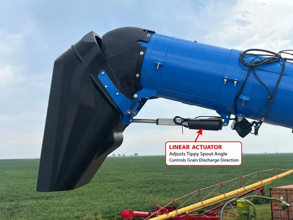
How an Electric Linear Actuator Adjusts an Unloading Auger Tippy Spout
Learn how an electric linear actuator can adjust an unloading auger tippy spout to improve grain discharge direction and trailer loading control.
Read Article →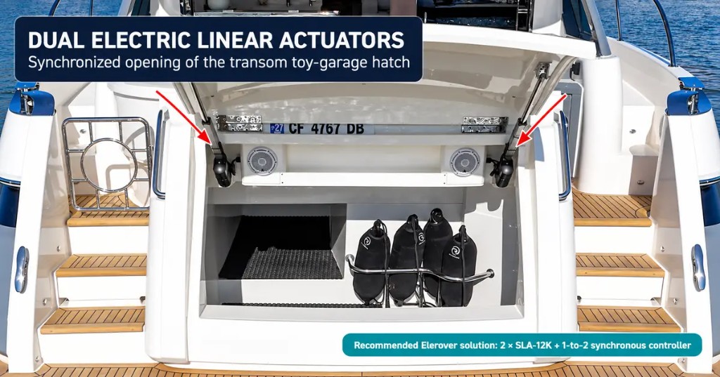
Dual Linear Actuators for Yacht Toy-Garage Hatches | SLA-12K
See how two synchronized electric linear actuators can open a yacht transom toy-garage hatch and how Elerover configures the SLA-12K system.
Read Article →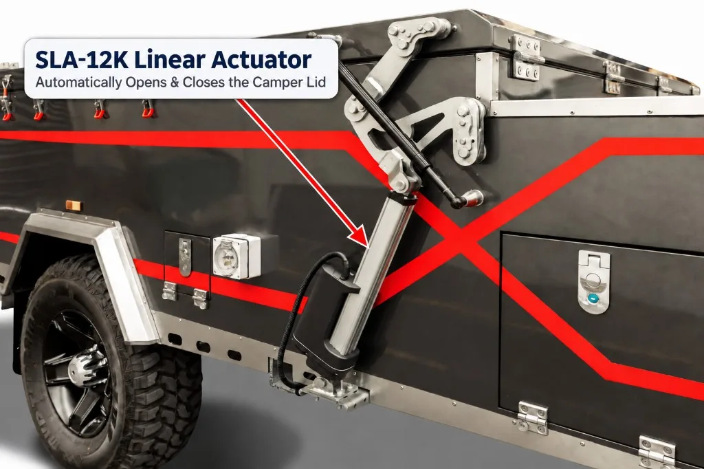
SLA-12K Linear Actuator for Automatic Camper Trailer Lids
See how a 12V or 24V SLA-12K heavy-duty linear actuator can automate the opening and closing of camper trailer lids and folding roof systems.
Read Article →